
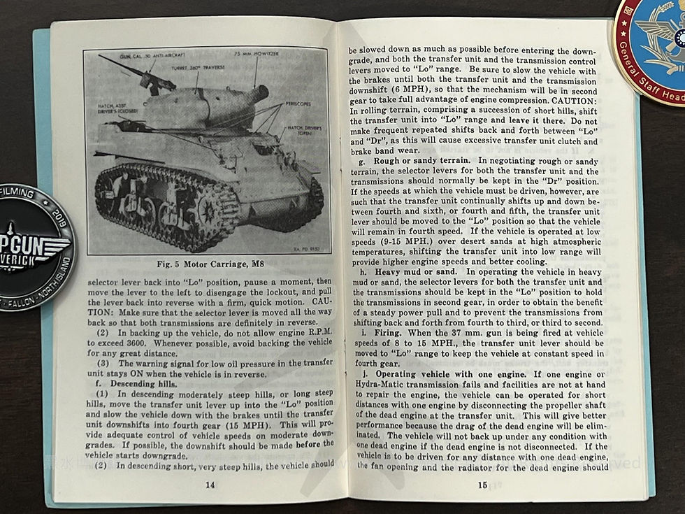
DRIVING INSTRUCTIONS, Light Tank, M5, M5A1 Motor Carriage, M8 - RESTRICTED, 1942
- 2022年7月31日
- 讀畢需時 28 分鐘
已更新:2022年8月3日
DRIVING INSTRUCTIONS, Light Tank, M5, M5A1 Motor Carriage, M8 - RESTRICTED, Prepared by Cadillac Motor Car Division General Motors Corporation - Detroit, Michigan - December 14, 1942《Black Water Museum Collections | 黑水博物館館藏》


CONTENTS
Controls...............................3
Driving Instructions.............8
Maintenance Hints.............17
Hydra-Matic Drive.............19
Questions and Answers......24
Copyright, 1942
General Motors Corporation Printed in U. S. A.
Revised December 14, 1942 Reprinted May 5, 1943

CONTROLS
1. SWITCHES AND INSTRUMENTS.
In designating instruments, the instrument on the right hand side of the instrument panel applies to the engine on the right-hand side of the vehicle and vice versa.
a. Master battery switch. The master battery switch is located on the front edge of the apparatus box on the left-side of the hull. When in the "Off" position, it disconnects all elec trical circuits. Pull switch handle out to turn from "Off" to "On," or from "On" to "Off."
NOTE: Never pull master switch to stop engines; always use ignition switches. If master switch is pulled, engines will not stop and generators will be ruined.
b. Ignition switches. The ignition switches are located on the outside corners of the instrument panel (Fig. 1). There are two switches-one for each engine.
c. Starter button. The starter buttons are located in the lower area of each instrument panel. There are two buttons one for each engine. The ignition must be on when cranking the engine.
d. Oil pressure gauges. There are two oil pressure gauges -one for each engine-located on each side of the instrument panel. The gauges operate electrically, with the circuits con nected to oil pressure units on the engines.
e. Temperature gauges. There are two temperature gauges one for each engine-located at the side center of the instrument panel. These gauges are connected electrically to the thermal units on the engines.
f. Warning signals. Warning signals on engine tempera ture and pressure are located-one on each side-in the lower area of the instrument panel. A red light flashes if oil pressure drops below twelve pounds or engine temperature in creases above 240° F (115.6 degrees Celsius). Reference must then be made to the oil and temperature gauges to determine exactly what is wrong. Three warning signals are also located along the lower edge of the instrument panel, one for each transmission and one for the transfer unit. A red light in any of these indicates dangerously low oil pressure (below 60 lbs.).


g. Tachometers. There are two tachometers-one for each engine-located in the upper outside corners of the instrument panel and geared to the distributor drive shafts. These instruments indicate the speed of each engine in R.P.M.'s and also indicate total R.P.M.'s each engine has been operated.
h. Ammeter. The ammeter is located in the left center of the instrument panel and connected so as to indicate the amount of charge or discharge in the main battery circuit.
i. Voltmeter. The voltmeter is located at the right center of the instrument panel. It indicates the voltage in the main battery circuit.
j. Speedometer. The speedometer is located in the lower center of the instrument panel. It indicates the speed of the vehicle and the mileage traveled.
k. Lighting switches. The use of the lighting switches is covered in Paragraph 3.
l. Siren switch. The siren switch is located on the floor of the driving compartment. (See Fig. 2.) A reset button for use in case the siren circuit breaker opens is located on top of the instrument panel as shown in Fig. 1. Dafting controls
2. DRIVING CONTROLS.
The steering brake levers and the accelerator in this vehicle are duplicated to provide for dual control. Other controls are not duplicated.
a. Accelerator. Individual foot accelerators are provided for the driver and assistant driver for dual control of the vehicle. Each accelerator controls both engines. The hand throttle is on the driver's side, located just above the instru ment panel where it can be reached by the assistant driver (Fig. 2). The hand throttle is self-locking in any position and is released by means of a spring button in the center of the control knob. CAUTION: Assistant driver's accelerator pedal should be turned back when not in actual use.
b. Choke. An automatic choke mechanism located on the carburetors provides the correct fuel mixture for starting the engines. This simplifies the starting procedure, which is given in Paragraph 5.
c. Spark control. The spark control is provided by means of centrifugal weights in the distributor. It is fully auto matic, being governed by engine speed, and requires no atten tion whatever from the driver.
d. Steering levers. Dual steering levers for the driver and assistant driver are mounted on the upper front deck of the vehicle. To steer the vehicle pull the lever on the side toward which it is desired to turn. See Paragraph 6 for detailed information on steering. Either set of levers may be swung forward when they are not being used.
e. Brakes. Pulling back simultaneously on both steering levers slows down or stops the vehicle, depending on the effort applied. The stop light goes on when both levers are pulled back, provided the lighting switch is in any position other than "Off." Parking brake controls on the left-hand or driver's steering levers permit these levers to be locked in the "On" position. Move the controls to the right for unlocking, to the left for locking the levers.
f. Clutch. There is no clutch pedal. Due to the fluid coupling between the engines and the transmissions, and the automatic features of the transmissions, there is no need for a foot-operated clutch.

g. Shifting controls.
(1) The driver does not shift gears with the Hydra-Matic transmissions. Gear changes are controlled by engine load and accelerator position, and are made automatically by hy draulic governors.
(2) Two controls are provided, however, for specific uses: a transmission selector lever and a transfer unit control lever. The transmission selector lever is provided so that the transmissions can be put in neutral, or forward driving range, or low range to use engine compression for braking, or reverse. The transfer unit control lever has driving and low range positions.
(3) The driving range positions, labeled "Drive" on both the transmission and transfer unit levers, are used for normal forward driving. With the controls in these positions, the vehicle will start up from a standstill in low gear and the mechanism will shift up automatically through the successive gears to sixth (direct drive) as the vehicle speed increases. The mechanism will also downshift automatically to lower gears as vehicle speed is reduced, either because the accelerator pedal is released or due to an upgrade.

3. LIGHTING CONTROLS.
Exterior driving lights are controlled from a single push pull button on the instrument panel. There are three positions in addition to "Off." A push-button lock on the control itself prevents the service lights from being turned on ac dentally. The light switch operates as follows:
a. Pull button out to first stop. This turns on the black out marker lights and permits the use of the blackout driving light as outlined in "f."
b. Depress locking button and pull switch out to second position. This turns on service headlight, tail light and stop light.
c. Depress locking button and pull switch out to last position. This operates the service stop light only.
d. Instrument panel lights are controlled by a rheostat switch, shown in Fig. 1. The intensity of instrument panel illumination is varied by merely rotating the button.

e. Interior lighting is provided by two dome lamps. One is located on the bottom of the ventilating fan and the other is located on the turret roof. These lights are operated by a toggle switch at the light itself.
f. The blackout driving light is operated by pulling the main lighting switch out to its first position, then pulling out the blackout light switch at the lower edge of the instrument panel. The locking button on this switch must be depressed before the switch can be operated. The blackout driving light is a separate lamp which must be inserted in the socket in place of the left headlamp. Intensity of the blackout driving light is controlled by a variable resistor on the top of the dif ferential case. Decrease intensity of this driving light on very dark nights when glow becomes too readily noticeable.
DRIVING INSTRUCTIONS
4. FUEL REQUIRED.
Only gasoline with an octane rating of 80 or above can be safely used in this vehicle. The engines should not detonate (knock); if they do, it indicates either that the gasoline is of incorrect grade, or that the spark timing is incorrect.
NOTE: It is important to turn the gasoline shut-off valve on before attempting to start the engine, and equally important to turn it off when the engines are stopped.
5. STARTING INSTRUCTIONS.
a. Normal starting. Under normal conditions the engines should be started according to the following procedure:
(1) Set the brakes.
(2) Depress the accelerator pedal 1/4 - 1/2 of full travel. Do not pump accelerator.
(3) Place transmission selector lever at neutral.
(4) Turn on the ignition switches for both engines.
(5) Press starter button for each engine until the engine fires. CAUTION: Both engines should be started at the same time, except at sub-zero temperature.
b. Engine check-up.
(1) As soon as the engines are started, the oil gauges should be observed. Pressure at idling speed should be about 15 pounds, at operating speed about 30 pounds. If the gauges do not indicate oil pressure within one minute, the engines should be shut off and an investigation made. Do not drive vehicle while engine or transmission warning signals are red. NOTE: The transfer unit signal will remain red until the vehicle has started to go forward. It remains lighted in reverse paul.
(2) The ammeter should also be watched to see that the generators are charging. If the ammeter does not indicate "+" with the engines idling, speed up engines by momentarily depressing accelerator. If ammeter needle does not move to "+" side, look for slipping generator belts or broken connections.
(3) The temperature gauges should indicate between 150° and 240° after the engines are warmed up, depending on operating conditions. If temperature exceeds 240° at which warning signal lights, stop engines and investigate for loss of coolant. CAUTION: When removing a filler cap from a hot radiator, always vent the radiator long enough to let all steam pressure escape before removing the cap, otherwise there is a possibility of serious personal injury. To vent radiator, turn the cap to the left (counterclockwise|逆時針) until the first stop is reached. After the cap has remained in this position one-half minute, or long enough to vent radiator thoroughly press down on cap to clear stop and turn further to left to remove it. When reinstalling a radiator cap, be sure cap is turned all the way to the right (clockwise|順時針) so that the entire cooling system will be sealed while operating.

(4) Check for loose parts.
(5) Check for unusual noises in each power train and engine.
c. Engine warm-up. During mild weather operation the engines must be warmed up to a point where instruments indicate satisfactory operation. At temperatures below freezing, the warm-up periods listed in step "f" should be observed.
d. Flooded engines.
(1) If the engines do not start readily in mild or warm weather, the most likely cause is a flooded condition in the carburetor or intake manifolds. This can be corrected by fully depressing the accelerator and then cranking the engines. As soon as the engines start, the throttle should be closed to prevent "racing" of the engines.
(2) Flooding usually occurs more severely in one engine, so that one engine starts and the other does not. In this case, the one engine that is operating should be shut off, the accelera tor pressed all the way down, and the flooded engine cranked until it starts. The other engine can then be restarted with a minimum of "racing" either engine. The accelerator pedal should not be pumped.
e. Starting hot engines. When starting hot engines, the accelerator pedal should be held halfway open or wider; other wise the procedure is the same.
f. Cold-weather starting and warm-up.
(1) The procedure for starting the engine in cold weather (temperatures down to 30° F. below zero) is the same as the normal starting procedure, except that engines should be started one at a time. Engines will not start at the lower temperatures, however, unless they are in good mechanical condition and lubricated with the proper grade of light engine oil, and unless the battery is fully charged.
(2) When the engines have started, allow them to run at 800-900 R.P.M. for four or five minutes, to allow the oil to warm up before depressing the throttle further. This should be done with the Hydra-Matic selector lever in neutral. Then shift the selector lever to "Dr" and allow the engines to idle for several minutes more to warm up the oil in the transmis sions. Do not drive the vehicle over five miles per hour for at least ten minutes after starting, to permit the oil in the trans fer unit and controlled differential to warm up.
g. Starting one engine with the other. If only one engine starts readily, it can be used to start the other engine by sim ply driving the vehicle a short distance at low speeds with the ignition switch of the "dead" engine turned on. CAUTION: First inspect dead engine to make sure it turns over freely before attempting to start it by use of other engine.

6. DETAILED DRIVING INSTRUCTIONS.
a. Normal shift control.
(1) For driving on roads or on smooth level terrain, the transmission selector lever should be moved to the "Dr" position (after the engines are started and while they are idling), and the transfer unit control lever should be moved rearward to the "Dr" position also. Selector lever must be pulled to left to disengage lock-out before it can be moved out of "Neutral." The transmissions are then "in gear," but to start the vehicle moving forward, the parking brake controls on the driver's levers must be released and the accelerator pedal depressed. The amount the pedal is depressed will determine the speed with which the vehicle moves forward.
(2) With this arrangement of the controls, the vehicle will start out in first gear and the transmission and transfer unit will automatically shift into second, third, fourth, fifth, and sixth as vehicle speed increases and engine load is reduced. As the vehicle loses speed either because the accelerator pedal is released or due to upgrades, the transmissions and transfer unit will shift down automatically to a lower gear.
(3) When ascending moderate grades, pressing the accelerator all the way down not only allows the engines to develop full power, but also causes the transmissions to downshift from sixth to fifth gear for better performance as soon as the vehicle speed drops below 15 MPH.
(4) The correct gear for normal forward driving is thus provided automatically by the transmissions and transfer unit. Manual shifts for better control under extreme conditions are covered later in this section.
b. Steering. To steer the vehicle, pull back on the right hand steering lever to make a right turn, or on the left-hand lever for a left turn. The lever that is being used should be applied firmly and then released fully, and this action repeated if necessary. The lever should not be held in a slightly applied position for long periods of time. CAUTION: It is very important that the steering levers be held far enough forward to insure complete release of the bands at all times except when steering or stopping; otherwise the brake lining wear will be excessive.
c.Stopping.
(1) To stop the vehicle, release the accelerator and pull back on both levers at the same time. There is no clutch to disengage. Both levers should be pulled back and engaged with heavy pressure and then released fully. If the stop is to be made from relatively high speed, it is advisable to use heavy pressure intermittently rather than a continuous but lighter pressure.
(2) In stopping on downgrades, the transfer unit control lever may be moved forward to the "Lo" position. This will shift the vehicle from sixth to fourth gear, increasing considerably the braking effect of engine compression. If this change in lever position is made when the vehicle is traveling at high speed, the mechanism will not downshift until the speed has been reduced (by use of the brakes) to a point where the shift can be made without undue strain on the transmissions or transfer unit. (15 MPH.) CAUTION: Do not use the transfer unit "Lo" range for repeated stops on level ground. or to assist brakes when stopping from high speed. Excessive use of transfer unit as a brake will cause premature wear of transfer unit bands, which cannot be replaced as easily as the steering brake shoes.
d. Ascending hills.
(1) When ascending moderately steep hills from a running start on level ground, take as much advantage as possible of the momentum acquired on the level. As the vehicle climbs the hill and loses speed due to the power demanded, the power train will automatically shift down, from sixth to fifth, to fourth, etc., as required.
(2) When ascending very steep hills with a running start, shift the transfer unit control lever to "Lo" before the vehicle speed drops below 15 MPH, and shift the Hydra-Matic selector lever to "Lo" before the speed drops below 6 MPH. Moving the transmission selector lever to "Lo" causes the trans missions to shift down to second gear sooner than otherwise and assures more rapid ascent.
(3) In ascending steep hills from a standing start, it is recommended that both the transfer unit and the transmission selector levers be placed in "Lo."
e. Reverse.
(1) To operate the vehicle in reverse, first bring it to a complete stop if it is in motion. Then move the transmission selector lever back into "Lo" position, pause a moment, then move the lever to the left to disengage the lockout, and pull the lever back into reverse with a firm, quick motion. CAU TION: Make sure that the selector lever is moved all the way back so that both transmissions are definitely in reverse.
(2) In backing up the vehicle, do not allow engine R.P.M. to exceed 3600. Whenever possible, avoid backing the vehicle for any great distance.
(3) The warning signal for low oil pressure in the transfer unit stays ON when the vehicle is in reverse.
f. Descending hills.
(1) In descending moderately steep hills, or long steep hills, move the transfer unit lever up into the "Lo" position and slow the vehicle down with the brakes until the transfer unit downshifts into fourth gear (15 MPH). This will provide adequate control of vehicle speeds on moderate down grades. If possible, the downshift should be made before the vehicle starts downgrade.
(2) In descending short, very steep hills, the vehicle should be slowed down as much as possible before entering the down grade, and both the transfer unit and the transmission control levers moved to "Lo" range. Be sure to slow the vehicle with the brakes until both the transfer unit and the transmission downshift (6 MPH), so that the mechanism will be in second gear to take full advantage of engine compression. CAUTION: In rolling terrain, comprising a succession of short hills, shift the transfer unit into "Lo" range and leave it there. Do not make frequent repeated shifts back and forth between "Lo" and "Dr", as this will cause excessive transfer unit clutch and brake band wear.
g. Rough or sandy terrain. In negotiating rough or sandy terrain, the selector levers for both the transfer unit and the transmissions should normally be kept in the "Dr" position. If the speed s at which the vehicle must be driven, however, are such that the transfer unit continually shifts up and down be tween fourth and sixth, or fourth and fifth, the transfer unit lever should be moved to the "Lo" position so that the vehicle will remain in fourth speed. If the vehicle is operated at low speeds (9-15 MPH.) over desert sands at high atmospheric temperatures, shifting the transfer unit into low range will provide higher engine speeds and better cooling.
h. Heavy mud or sand. In operating the vehicle in heavy mud or sand, the selector levers for both the transfer unit and the transmissions should be kept in the "Lo" position to hold the transmissions in second gear, in order to obtain the benefit of a steady power pull and to prevent the transmissions from shifting back and forth from fourth to third, or third to second.
i. Firing. When the 37 mm. gun is being fired at vehicle speeds of 8 to 15 MPH., the transfer unit lever should be moved to "Lo" range to keep the vehicle at constant speed in fourth gear.
J. Operating vehicle with one engine. If one engine or Hydra-Matic transmission fails and facilities are not at hand to repair the engine, the vehicle can be operated for short distances with one engine by disconnecting the propeller shaft of the dead engine at the transfer unit. This will give better performance because the drag of the dead engine will be eliminated. The vehicle will not back up under any condition with one dead engine if the dead engine is not disconnected. If the vehicle is to be driven for any distance with one dead engine, the fan opening and the radiator for the dead engine should be covered to insure proper cooling of the operating engine.

7. STOPPING THE ENGINES.
a. To stop the engines, close the throttle until the engines are idling at approximately 425 R.P.M., and run at this speed for three or four minutes, then turn off both ignition switches. Finally, open master battery switch. CAUTION: Always turn off the ignition switches before opening master battery switch.
b. If the vehicle is not to be started again within a very short time, close the gasoline shut-off valve at the fuel filter.
8. TOWING INSTRUCTIONS.
a. Equipment. A towing shackle is mounted on each corner of the hull of the vehicle about 20 inches from the ground. Two of these shackles are mounted in front and two in the rear. These shackles provide a quick method of attaching either the towing bar or cables,
b. Precautions. When towing a vehicle, there are several precautions that must be taken:
(1) When towing a vehicle that is disabled due to engine conditions only, and is known to have Hydra-Matic transmissions and transfer unit in good working order, the vehicle can be safely towed forward at speeds not to exceed 10 MPH., provided the transmission selector lever is in neutral.
(2) If the vehicle is disabled because of some difficulty with one Hydra-Matic transmission, the propeller shaft leading to that transmission must be disconnected at the front and before towing is attempted. In case of difficulty with the transfer unit, the tracks must be removed and the vehicle towed on the bogie wheels.
(3) A vehicle should never be towed backward, except for very short distances-never as much as 4-mile. The reason is that, when the vehicle is being towed backward, the oil pumps for the transfer unit and transmissions run back wards, and in consequence these units do not have the oil circulating under pressure and can easily be damaged beyond repair.
(4) Always check level of oil in transfer unit and Hydra Matic transmissions before towing.
MAINTENANCE HINTS
9. DAILY LUBRICATION.
The following lubrication items should be checked daily, or at every halt under conditions of severe operation:
a. Check oil level for each engine.
b. Check oil level for each transmission.
C. Check oil level of transfer unit and differential at filler on transfer unit case.
d. Check oil level in each final drive.
CAUTION: An accurate check can not be made of oil level in engines, transmissions or transfer case except where tank is level and has been operated sufficiently to warm up lubricants.
e. On Light Tanks, check oil level for auxiliary power plant. Complete lubrication instructions appear in TM 9-732, 727C and 732B, and in Chek-Chart No. 81.
10. DAILY COOLING INSPECTION.
The level of water in each cooling system should be checked at least daily, and the following precautions observed:
Removing Cap-When removing radiator cap from a hot system, turn cap counter-clockwise to first stop and leave there long enough to let all steam pressure escape; then press down and turn further to remove.
Inspecting Gasket-Every time water level is checked, in spect filler cap gasket to see that it is in place and in good condition. Missing or damaged gaskets must be replaced.
Installing Cap-Before installing radiator cap, check to see that filler neck gasket is in place, then install radiator cap by pushing down and turning it clockwise all the way to the right to seat cap properly. Unless above procedure is fol lowed, system will not be sealed, causing water loss and over heating.
Warning: Always have bulkhead doors closed when operating vehicles; otherwise air flow will by-pass radiators and overheating will result.
11. DRAINING AND FILLING COOLING SYSTEM.
Each cooling system is drained at three points: a plug at the bottom of each Hydra-Matic transmission, and two drain plugs at the fan end of each engine. All three plugs must be removed for complete draining of the system. It is also necessary to remove the radiator cap for rapid and complete draining of the system.
When filling the cooling system, add water or antifreeze as required, pouring in at moderate speeds to avoid spillage. If hot water is available, it will partly open the blocking-type thermostat and permit immediate filling of the system. If cold water is used, it may be necessary to run the engine for a few minutes before the thermostat valve opens and permits system to be completely filled. Be sure to perform this operation if the system seems full before 35 quarts (33L|公升) have been added.

12. ENGINE-TRANSMISSION TEST.
If one or both engines races, labors, or otherwise performs improperly, the following test will reveal whether it is due to an engine or transmission and which unit is at fault:
a. Start one engine only.
b. Shift Hydra-Matic selector lever to "Dr."
c. Pull steering levers as far back as possible so that vehicle will not move.
d. Gradually depress throttle pedal all the way.
e. Note speed of engine as shown on tachometer.
f. If the engine speed races up to 2500 to 3000 R.P.M., it means that the transmission bands are slipping. Engine speeds of 1400 to 1800 are normal. An engine that won't reach 1400 is in need of adjustment or repair.
CAUTION: Never drive vehicle if transmission bands are slipping.
g. Repeat test for other engine and transmission.
WARNING: Do not perform this test for longer than one minute at a time, to avoid overheating the transmission oil.
THE HYDRA-MATIC DRIVE
HOW IT WORKS
The Hydra-Matic Drive, as used in the Light Tank, M5, and Motor Carriage, M8, BWM is a recently developed and highly effi cient means of transmitting power from the engines to the tracks or wheels of a vehicle.
The Hydra-Matic Drive takes the place of two conventional mechanical units which require considerable driver effort to operate. These units are the clutch, whose function is replaced by the cushioning effect of the Hydra-Matic fluid coupling, and the transmission.
As used in M5 and M8 vehicles, the Hydra-Matic Drive ar rangement includes two transmissions, one for each engine, and a transfer unit, which combines the power output of the two engines and also supplies a two-speed gearing. The four speed transmissions, in combination with the two-speed trans fer unit, provide six forward speeds. These units have auto matic shifting features which keep the engines operating in the speed range in which maximum power is developed.
The automatic shifting features of the Hydra-Matic Drive simplify driving by eliminating the physical effort of shifting gears from one ratio to another, and also by supplementing to a considerable degree the driver's judgment as to when the shifts should be made. When the vehicle starts from a full stop, the mechanism will automatically shift through first, second, third, fourth, fifth, and up to sixth or direct drive.
In order to permit complete driver control of the vehicle, shifting is completely automatic, but it depends not simply on vehicle speed but also upon the driver's demand for performance. The timing of the automatic shifts is determined by two major factors: The speed of the vehicle, and the throttle opening, which is in turn determined by the position of the acceler ator. With light accelerator pressure, the shifts occur at relatively low speeds; with wide open throttle, the shifts occur at higher speeds.
Manual controls are provided, consisting of a transmission selector lever and a transfer unit control lever for the follow ing specific uses:

(1) To put the transmission in neutral for starting the engines or running them on test.
(2) To put the transmission in either forward or reverse.
(3) To put the transmission or transfer unit in low range to permit maximum use of engine compression as a brake when descending hills.
CONSTRUCTION.
The Hydra-Matic Drive consists essentially of two planetary gear trains with a fluid coupling between them, and an additional planetary unit at the rear to provide reverse gear. The fluid coupling provides the slippage necessary to permit the vehicle to stand still when the engine is idling, and to cushion the shock of gear changes. Thus, it performs the function of a clutch.
The fluid coupling consists of two rotors, or torus members, each splined to an independent shaft. When the driving torus member is rotated, the oil that it contains flows radially out ward and crosses over to the driven torus member (Fig. 6). In doing this, the fluid sets up a driving force that causes the driven torus to rotate at nearly the same speed as the driving torus.
Each of the planetary units consists of three planet gears which encircle and are meshed with a center gear, and which are in turn surrounded by a gear having internal teeth in its inner circumference. One member of this planetary system can be kept from rotating by a band wrapped around an integral drum. This band is applied or released by a servo mechanism which is simply a double-acting piston and cylinder operated by oil pressure. Each planetary unit also incorporates a multi ple disc clutch which is applied by oil pressure and released ch which is applied by oil by springs.
When the clutch is released and the band applied, the planet gears are forced by the driving gear to "walk around" the gear that is held stationary; consequently, the output shaft which is connected to the planet gears is driven at reduced speed and the unit is in reduction BWM (Fig. 7).

When the band is released and the clutch is applied, the entire mechanism is locked together so that it rotates as a unit (Fig. 8).
Each of the planetary gear trains is thus a complete, two speed transmission in itself, as it can operate either in reduction or in direct drive. The transmissions each contain two of these planetary gear trains; the transfer unit contains one. The sixx vehicle speeds are secured from these three planetary units by means of the combinations shown in Fig. 10.
The speeds at which the gear changes occur are controlled by oil pressure to a control valve mechanism. Briefly, this mechanism consists of balanced shift valves against which pressure is exerted at one end in proportion to the amount the accelerator pedal is depressed, and at the other end by pressure from a centrifugal governor which exerts pressure in direct proportion to the speed of the vehicle (Fig. 9). With this arrangement, when the vehicle speed reaches a certain point in relation to the accelerator position, the transmission upshifts. When the vehicles speed decreases due to brake action, or to ascending a hill, a point is reached when the accelerator pedal pressure against the shift valve causes the transmission to shift to a lower gear.

SPEED RANGES
This chart shows the range of vehicle speeds in each speed or gear. These speed ranges overlap because the automatic up and-down shifts vary with throttle opening. The selector levers do not shift any gears themselves, but simply limit the number of speeds through which the drive automatically shifts.
Transmission Lever Position | Dr (Drive) | Dr (Drive) | Lo (Low) |
Transfer Unit Lever Position | Dr (Drive) | Lo (Low) | Lo (Low) |
Speed (檔位) | Vehicle Speed m.p.h. | Vehicle Speed m.p.h. | Vehicle Speed m.p.h. |
1st | 0-3 (0-4.8 km/h) | 0-3 (0-4.8 km/h) | 0-5 (0-8 km/h) |
2nd | 2-6 (3.2-9.7 km/h) | 2-6 | 2-6 (Max.) |
3rd | 3-12 (4.8-19.3 km/h) | 3-12 | |
4th | 4-15 (6.4-24.1 km/h) | 4-15 (Max.) | |
5th | 8-29 (12.9-46.7 km/h) | | |
6th | 8-40 (Max.)(12.9-64.4 km/h) | | |
Warning: Never drive over 15 m.p.h. in Transfer Unit Low range, or over 6 m.p.h. in Transmission Low Range.
QUESTIONS & ANSWERS
WHAT EVERY TANK DRIVER SHOULD KNOW DRIVING
1. Q. List the 5 items to be performed when starting the engines under normal conditions.
A. 1. Set the brakes; 2. Depress the accelerator pedal about to ½ open; DO NOT PUMP ACCELER ATOR!! 3. Place Hydra-Matic selector lever in neutral position; 4. Turn on both ignition switches; 5. Press starter buttons for both engines, starting both engines at the same time, while observing tachometers.
2. Q. What checks should be made as soon as engines start?
A. Check oil pressure gauges for oil pressure and the ammeter for generator charging rate.
3. Q. How long should the engines be warmed up in mild weather before moving vehicle?
A. Just long enough to see that oil pressures are up and generators are charging.
4. Q. How would you start a flooded engine?
A. Push foot accelerator wide open and press starter button. As soon as engine starts, release throttle in order to prevent racing. NOTE: If one engine only and is flooded, shut off other engine before opening throttle.
5. Q. What is the best method of starting a hot engine?
A. Open throttle half way while pushing starter button.
6. Q. If the starting motor was inoperative on one engine, how could you start that engine?
A. Place transmission selector lever in DR position and drive vehicle forward with one engine at about 4 m.p.h. after turning ignition switch of dead engine into the "On" position.
7. Q. If one engine or Hydra-Matic transmission fails, what two things are necessary before you could bring the tank in on one engine?
A. Disconnect dead engine driveshaft at transfer unit end. Cover fan opening and radiator of dead engine.
8. Q. Describe the method of starting the engines by towing the tank.
A. With Hydra-Matic selector lever in "neutral," and transfer unit lever in "Lo," tow tank at 4 to 5 m.p.h. Turn on ignition switches, press foot accelerator, move Hydra-Matic selector lever to DR position, and con tinue towing until engines fire.
9. Q. How would you start the engines if the battery was discharged to a point where the starting motors would not operate?
A. Start auxiliary power plant and charge battery for a few minutes-then start engines with auxiliary power plant running.

10. Q. If the battery was discharged to a point where it would not crank the auxiliary power plant, how would you start the auxiliary power plant engine?
A. Turn engine over with starting rope while holding the starting button in the ON position.
11. Q. How long should hot engines be idled before stopping them?
A. When temperature indicators read over 200°, idle engines at 1000 r.p.m. until indicators read 200°.
12. Q. What two things should the driver always do after shutting off the engines?
A. Place master switch in "Off" position and close the gasoline shut-off valves.
13. Q. Whenever it is necessary to tow the vehicle due to engine failure, what is the correct procedure?
A. Place selector lever in neutral and do not tow faster than 10 m.p.h.
14. Q. Whenever it is necessary to tow the vehicle due to Hydra-Matic Transmission failure, what is the correct procedure?
A. Disconnect the driveshaft at the transfer unit end, place selector lever in neutral, and do not tow faster than 10 m.p.h.
15. Q. When it is necessary to tow the vehicle due to trans fer unit or controlled differential failure, what is the correct procedure?
A. Remove tracks and "chain up" the trailing idler wheels to the rear of the hull and tow vehicle on bogie wheels.
16. Q. Why should the vehicle never be towed more than 100 feet backwards?
A. Because the oil pumps in transmissions and transfer unit turn backwards and will not supply oil under pressure.
17. Q. What is the correct method of placing the HydraMatic Transmission in reverse?
A. With engines idling and tank at a standstill, move paul selector lever into LO position, pause a moment, then quickly move selector lever into reverse position.
18. Q. With the transfer unit lever in the LO position and the transmission selector lever in DR position, what is the maximum allowable vehicle speed?
A. 15 m.p.h. (24.1 公里/小時)
19. Q. With both the transfer unit and transmission selector levers in the LO position, what is the maximum allow able vehicle speed?
A. 6 m.p.h. (9.7 公里/小時)
20. Q. What is the best method of negotiating an extremely steep hill on very deep mud or sand?
A. Place both control levers in the LO position, but do not drive vehicle over 6 m.p.h.
21. Q. In what position should the transfer unit control lever be placed when driving over rough terrain when the vehicle speed is below 15 m.p.h.?
A. In the LO position, to prevent upshifting and downshifting of the transfer unit.
22. Q. What position of the transfer unit control lever would give the coolest running engines when driving over hot desert sands at speeds between 15 and 17 m.p.h.?
A. The LO position.
23. Q. How can the transfer unit control lever be used to slow down the vehicle when coming to a halt from high speed?
A. After slowing vehicle to speed of 17 to 18 m.p.h. with the brakes, place transfer unit control lever in the LO position.
24. Q. What precaution should the driver take when operating the vehicle with the transfer unit control lever in the LO position?
A. Observe the tachometers to see that engines are not operated over 3600 r.p.m., or do not drive tank over 15 m.p.h.
25. Q. What will cause the transmissions to downshift from 6th to 5th speeds when driving at speeds below 18 m.p.h.?
A. Pressing the foot throttle all the way down.

LUBRICATION(潤滑)
1. Q. What precaution should be observed when checking Hydra-Matic and transfer unit oil levels to prevent dirt entering filler tube?
A. Brush or wipe off dirt around top of tube and plunger, and handle plungers carefully while out of transmissions.
2. Q. Why is it necessary to check Hydra-Matic oil levels immediately after stopping engines?
A. To assure that fluid coupling is full and that the oper ating oil level is correct.
3. Q. Why should the vehicle be on level ground when checking transfer unit oil level?
A. Because the controlled differential and transfer unit are interconnected, and unless tank is level a misleading reading will show up on plunger.
4. Q. What should be done if it is necessary to add additional oil to transfer unit or transmission, or an unusual amount to engines?
A. Report to Commanding Officer; look for oil leaks; do not operate until investigated.
5. Q. What 3 points on the throttle linkage should be cleaned and lubricated frequently, in order to allow the transmissions to downshift when foot throttle is pushed to the floor?
A. Detent overrun mechanism on both carburetors, and at the transfer unit.
6. Q. Do the turret support bearings require lubrication, and what is the purpose of the hole in turret support bearing housing?
A. No. To allow water to drain out of housing.
AIR FILTERS(空氣濾清器)
1. Q. How many air filters are there in the M5 Tank, and what types are they?
A. Five-three oil bath and two oil wetted.
2. Q. Give the method of cleaning both types.
A. (Oil Bath) Clean reservoir and refill with fresh oil to proper level. Remove filter element; clean thoroughly all in cleaning solvent, blow out with compressed air, or let dry before replacing. (Oil Wetted) Clean filter in cleaning solvent; blow out or let dry, and wet filter with heavy engine oil before replacing.
3. Q. What effect would a high oil level in the reservoir of the carburetor air filters have on carburetion?
A. It would cause an excessively rich mixture on idle, and engines would not idle properly. ad dreamed
4. Q. Describe the path of the air stream from the fighting compartment to the carburetor? (One engine.)
A. The air enters the gasoline tank compartment through a slot in the hulkhead, over the top of the gasoline tank into the cleaner, through the cleaner to a pipe that leads to the carburetor.
5. Q. Name 6 possible points where excessive dust and dirt might enter the carburetor air stream either before or after entering air cleaner?
A. Holes in sponson floor, antenna mast plug, engine compartment cover joints, around air cleaner opening in bottom of sponson, air cleaner elbow gaskets, and hose connections on pipe from cleaner to carburetor.
6. Q. What one of the above 6 points should be checked every time air cleaner is cleaned?
A. The seal and fit of the covers on the sponson floors lous of beneath the air cleaners.
7. Q. What precaution must be always observed when reinstalling the carburetor air cleaner elements?
A. Position the element so that it is forced to its final position when the reservoir is installed.
8. Q. Name the place in the cleaner where it is possible for dirt and dust to form in such a manner as to restrict the air entering the cleaner.
A. In the throat of the cleaner between the inner and outer case.

9. Q. How is the dirt removed?
A. Use a brush or rod to clean out dirt between inner and outer case when reservoir is removed.
10. Q. What is the result on engine performance if the cleaner element is forced up too far in the case?
A. This restricts the air entering the cleaner, resulting in choking the engines at high speed.
11. Q. Where are the crankcase ventilator air cleaners located?
A. There are two positions. On early vehicles, they are beneath the left blocks of both engines. On later tanks, they are placed just over the left cylinder head of each engine.
12. Q. Where is the air cleaner for the auxiliary power plant located?
A. Just to the left of the left bulkhead opening in the engine compartment.
COOLING
1. Q. What inspections should be made on cooling system before starting engines?
A. Coolant level in radiators, condition of gaskets in radiator filler necks, water leaks at hose connections, cleanliness of radiator core air passages, and making sure radiator caps are locked in 2nd or sealed position.
2. Q. What two precautions should be observed when re moving radiator caps when engines are hot?
A. If engine temperatures are above 180°, allow to cool before removing cap. Turn cap to vented position and allow pressure to escape.
3. Q. What should you do if you find it necessary to add more than one gallon of water to an engine?
A. Report to Commanding Officer; look for water leak; aid do not drive tank until corrected.
4. Q. Why should the vehicle never be operated with the bulkhead doors removed?
A. This would allow fan air to bypass radiator cores, causing overheating.
5. Q. Why is it necessary to cover the fan opening of the dead engine when operating the vehicle on one engine?
A. The live engine fan would draw air in through the dead engine fan opening, bypassing the radiator core, and causing overheating.
6. Q. How can you determine if the radiator core air pas sages need cleaning?
A. Inspect cores through bulkhead vent doors, and through radiator neck opening in engine compartment cover.
7. Q. What is the purpose of the four small hinged doors at the top of the bulkhead? Why should they operate freely?
A. They allow the engine fans to draw air from the fight ing compartment, and they should operate freely so that they will open when the engines are running and close when the engines are stopped.
8. Q. What is the correct tension for the fan and generator belt?
A. 5/8"-3/4" slack midway between pulleys.
9. Q. What would happen if radiator filler neck gasket is left out or does not seal properly?
A. The water pump would force the water out of radiator filler neck and vent, causing overheating and damage to engine; and there would not be any pressure on coolant, causing a low boiling point which would result in further water loss.
10. Q. Name two openings in the hull that should never be blocked with bed rolls, tarpaulins, etc.
A. The two screened air intakes for the engine radiators.
11. Q. Why should the hose connection clamps be tightened after every 250 miles of operation?
A. To allow for "set" in the hose connections and prevent water leaks.

MISCELLANEOUS
1. Q. To what level should the gas tanks be filled?
A. To one inch below the upper holes in the flame arresters.
2. Q. What safety precaution should always be taken when engine compartment rear doors are open?
A.Make sure master switch is in the "OFF" position.
3. Q. Why should the master switch never be placed in the "OFF" position when the engines are running?
A. In order to avoid burning out generators and regulators.
4. Q. Will the auxiliary power plant charge the battery with the master switch in the "OFF" position?
A. No.
5. Q. When should the steering brakes be adjusted?
A. Whenever a pull of 15 pounds on lever handle brings lever back on quadrant more than 10 notches.
黑水博物館 | BLACK WATER MUSEUM | www.blackwater.tw | All Rights Reserved


留言