
TM 9-1729A M5、M5A1、M24輕型戰車 及M8、M19砲車,引擎、冷卻、供油系統維修技令,民國33年《Black Water Museum Collections | 黑水博物館館藏》
- 2023年10月27日
- 讀畢需時 4 分鐘
TM 9-1729A, WAR DEPARTMENT TECHNICAL MANUAL, ORDNANCE MAINTENANCE, LIGHT TANKS M5, M5A1, AND M24, 75-MM HOWITZER MOTOR CARRIAGE M8, AND TWIN 40-MM GUN MOTOR CARRIAGE M19: ENGINES, COOLING SYSTEMS AND FUEL SYSTEMS, 1944
TM 9-1729A M5、M5A1、M24輕型戰車 及M8、M19砲車,引擎、冷卻、供油系統維修技令,民國33年《Black Water Museum Collections | 黑水博物館館藏》


CHAPTER 4 FUEL SYSTEM
Section I DESCRIPTION AND DATA
25. GENERAL.
a. Description, 1G Series.
(1) This fuel system (fig. 85) consists of two 43-gallon fuel tanks located in the sponsons on each side of the engine compartment, from which lines lead to a combination filter. and shut-off valve on the left front of the bulkhead, and thence back to the mechanical fuel pumps, one on each engine, and up to the carburetors.
(2) An air cleaner is carried in a special compartment at the rear of each sponson. Air from the fighting compartment passes around the fuel tanks, through the oil and filtering elements of the cleaners and through carefully sealed air inlet tubes to the carburetors.
(3) The fuel system for the auxiliary power plant (used on M5, M5A1 vehicles only) consists of a fuel line from the left-hand tank (fig. 85), a separate filter and shut-off valve, and a line down to the carburetor on the auxiliary power plant. There is also a separate oil- bath air cleaner and air intake tube to the carburetor. There is no separate fuel tank for this system, and no fuel pump, as the system has a gravity feed.

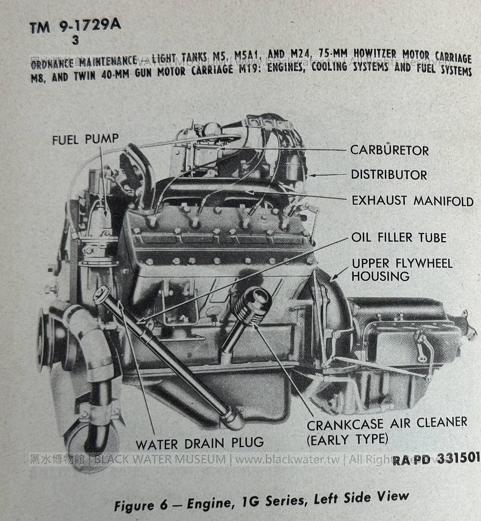
Figure 85 - Fuel System, M5A1, 1G Series


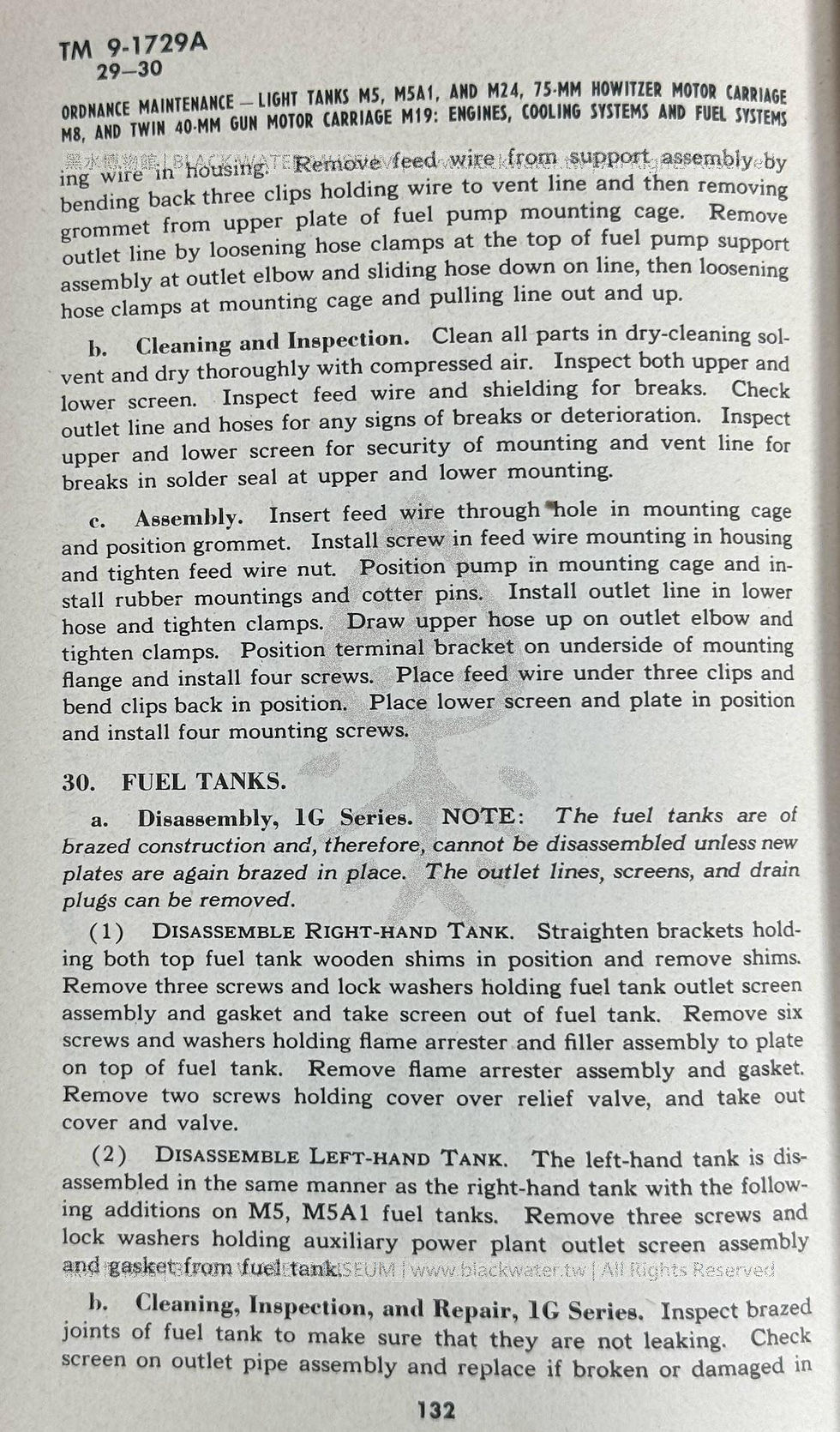
ing wire in housing. Remove feed wire from support assembly by bending back three clips holding wire to vent line and then removing grommet from upper plate of fuel pump mounting cage. Remove outlet line by loosening hose clamps at the top of fuel pump support assembly at outlet elbow and sliding hose down on line, then loosening hose clamps at mounting cage and pulling line out and up.
b. Cleaning and Inspection. Clean all parts in dry-cleaning sol- vent and dry thoroughly with compressed air. Inspect both upper and lower screen. Inspect feed wire and shielding for breaks. Check outlet line and hoses for any signs of breaks or deterioration. Inspect upper and lower screen for security of mounting and vent line for breaks in solder seal at upper and lower mounting.
c. Assembly. Insert feed wire through hole in mounting cage and position grommet. Install screw in feed wire mounting in housing and tighten feed wire nut. Position pump in mounting cage and in- stall rubber mountings and cotter pins. Install outlet line in lower hose and tighten clamps. Draw upper hose up on outlet elbow and tighten clamps. Position terminal bracket on underside of mounting flange and install four screws. Place feed wire under three clips and bend clips back in position. Place lower screen and plate in position and install four mounting screws.
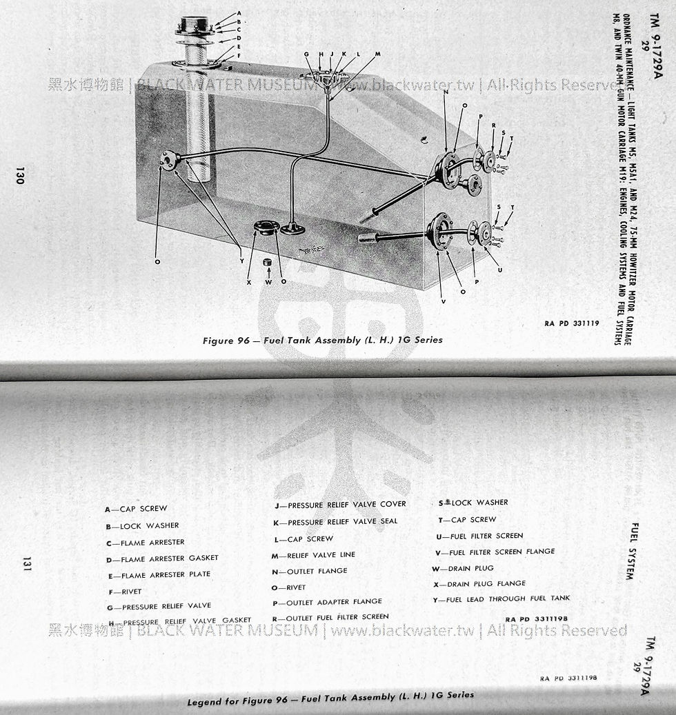
30. FUEL TANKS.
a. Disassembly, IG Series. NOTE: The fuel tanks are of brazed construction and, therefore, cannot be disassembled unless new plates are again brazed in place. The outlet lines, screens, and drain plugs can be removed.
(1) DISASSEMBLE RIGHT-HAND TANK. Straighten brackets holding both top fuel tank wooden shims in position and remove shims. Remove three screws and lock washers holding fuel tank outlet screen assembly and gasket and take screen out of fuel tank. Remove six screws and washers holding flame arrester and filler assembly to plate on top of fuel tank. Remove flame arrester assembly and gasket. Remove two screws holding cover over relief valve, and take out cover and valve.
(2) DISASSEMBLE LEFT-HAND TANK. The left-hand tank is dis- assembled in the same manner as the right-hand tank with the follow- ing additions on M5, M5A1 fuel tanks. Remove three screws and lock washers holding auxiliary power plant outlet screen assembly and gasket from fuel tank.
b. Cleaning, Inspection, and Repair, 1G Series. Inspect brazed joints of fuel tank to make sure that they are not leaking. Check screen on outlet pipe assembly and replace if broken or damaged in such a way that sediment in the fuel tank could pass into the fuel lines. Inspect relief valve assembly. Inspect the vent in the fuel tank filler cap to make sure it is open. Make sure that vent float does not stick. Inspect condition of mounting flanges on outlet pipe assembly and flame arrester inlet to make sure they are smooth and flat. Remove any nicks or burs with a fine file. Clean according to procedures in TM 9-1726F.
FUEL SYSTEM
C. Assembly, 1G Series.
(1) ASSEMBLE RIGHT-HAND TANK. Position a new flame arrester and filler assembly gasket on top of fuel tank. Install flame arrester and filler assembly in fuel tank and install six screws and washers holding assembly to tank. Install drain plug in bottom of fuel tank. Install relief valve gasket and cover. Position a new fuel tank outlet screen assembly gasket on front end of fuel tank and install outlet screen assembly in front of tank. Install three screws and lock wash- ers holding screen assembly to tank. Position both top fuel tank wooden shims in position on tank, and bend brackets over notches in shims.
(2) ASSEMBLE LEFT-HAND TANK. NOTE: The left-hand tank is assembled in exactly the same manner as the right-hand fuel tank with the following additions. Position a new auxiliary power plant outlet screen assembly gasket on front end of fuel tank and position outlet screen assembly in fuel tank (M5, M5A1 only). Install the three screws and lock washers which hold auxiliary plant outlet screen assembly to flange on fuel tank (M5 only).


留言